隔离型栅极驱动 耐用、强大、精准的单通道和双通道隔离型栅极驱动器IC
EiceDRIVER™隔离型栅极驱动器专为有高性能和耐用性需求的应用而设计,例如,太阳能逆变器、电动汽车(EV)充电器、工业驱动装置、汽车、储能系统(ESS)、不间断电源(UPS)、服务器和电信SMPS。
隔离型栅极驱动器可提供高达18 A的输出电流、较短的传输延时和延迟匹配(7 ns)、300 kV/μs共模瞬态抗扰度(CMTI)和宽栅极电压(40 V),以实现具有负栅极电压的正负电源,是先进的SiC MOSFET和 GaN开关的理想之选。
紧凑型和增强型EiceDRIVER™属于广为人知的隔离型驱动器系列之一。紧凑型EiceDRIVER™是易于设计的简易隔离型栅极驱动器,具有两级电压转换速率控制和米勒钳位功能,采用DSO-8等小型封装。增强型EiceDRIVER™则具备一些高级功能,例如,短路保护(DESAT)和软关断、米勒钳位以及通过I2C配置多个参数,以便快速进行原型设计和条件监测,从而实现预知性维护。
EiceDRIVER™隔离型栅极驱动器采用磁耦合无磁芯变压器(CT)技术,可跨电气隔离进行信号传输。得益于CT技术,我们提供了功能隔离、基本绝缘和加强绝缘,并通过UL 1577(VISO = 5.7 kV)和VDE 0884-11(VIORM = 1767 V)认证。其中,功能隔离可达2300 V,适用于1500 V DC应用中的2kV CoolSiC™。
高级保护
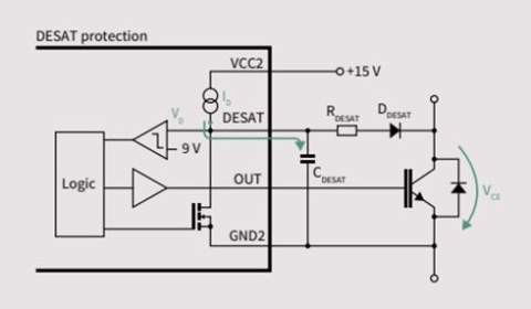
- 通过精确的退饱和(DESAT)检测电路(电流源和比较器)进行可靠的短路检测:防止功率开关在短路时受损
- 软关断:用于短路电流保护,旨在降低集电极-发射极电压过冲
- 内置短路钳位:通过降低栅极电压来限制短路电流
- 有源米勒钳位:防止由于高dV/dt导致的寄生导通
| 主要特性 | 主要优势 |
|
|
Certificates
| Part Numbers | UL 1577 (Vrms) | VED0884-11 Reinforced |
EN 60950-1* |
EN 62368-1 | EN 61010-1 | GB4943.1 | |||||
| 2250 | 2500 | 3000 | 5700 | Basic | Reinforced | Basic | Reinforced | ||||
| 2EDS8165H | √ | √ | √ | √ | √ | ||||||
| 2EDS8265H | √ | √ | √ | √ | √ | ||||||
| 2EDS9265H | |||||||||||
| 2EDF7275F | |||||||||||
| 2EDF7175F | |||||||||||
| 2EDF9275F | |||||||||||
| 2EDF7275K | |||||||||||
| 2EDF7235K | |||||||||||
| 2EDR8259H | √ | √ | √ | √ | |||||||
| 2EDR7259X | √ | √ | √ | √ | |||||||
| 2EDR8259X | √ | √ | √ | √ | |||||||
| 2EDR9259X | √ | √ | √ | √ | |||||||
| 2EDB8259F | √ | ||||||||||
| 2EDB7259Y | √ | ||||||||||
| 2EDB8259Y | √ | ||||||||||
| 2EDB8259Y | √ | ||||||||||
| 2EDB7259K | √ | √ | √ | ||||||||
| 2EDB8259K | √ | √ | √ | ||||||||
| 2EDB7259A | √ | √ | √ | ||||||||
| 2EDB8259A | √ | √ | √ | ||||||||
| Part Number | UL 1577 (Vrms) | VDE0884-11 | |
| 3000 | 5700 | Reinforced | |
| 1ED3120MC12H | √ | √ | |
| 1ED3121MC12H | √ | √ | |
| 1ED3122MC12H | √ | √ | |
| 1ED3123MC12H | √ | √ | |
| 1ED3124MC12H | √ | √ | |
| 1ED3131MC12H | √ | √ | |
| 1ED3431MC12M | √ | √ | |
| 1ED3461MC12M | √ | √ | |
| 1ED3491MC12M | √ | √ | |
| 1ED3830MC12M | √ | √ | |
| 1ED3860MC12M | √ | √ | |
| 1ED3890MC12M | √ | √ | |
| 1ED3120MU12H | √ | ||
| 1ED3121MU12H | √ | ||
| 1ED3122MU12H | √ | ||
| 1ED3123MU12H | √ | ||
| 1ED3124MU12H | √ | ||
| 1ED3131MU12H | √ | ||
| 1ED3431MU12M | √ | ||
| 1ED3461MU12M | √ | ||
| 1ED3491MU12M | √ | ||
| 1ED3830MU12M | √ | ||
| 1ED3860MU12M | √ | ||
| 1ED3890MU12M | √ | ||
| 1ED3124MU12F | √ | ||
| 1ED3125MU12F | √ | ||
| 1ED3240MC12H | √ | √ | |
| 1ED3241MC12H | √ | √ | |
| 1ED3250MC12H | √ | √ | |
| 1ED3251MC12H | √ | √ | |
| 1ED3320MC12N | √ | √ | |
| 1ED3321MC12N | √ | √ | |
| 1ED3322MC12N | √ | √ | |
| 1ED3323MC12N | √ | √ | |
| 1ED3140MU12F | √ | ||
| 1ED3141MU12F | √ | ||
| 1ED3142MU12F | √ | ||
| 1ED3127MU12F | √ | ||
Part Numbers |
UL 1577 (Vrms) | VDE0884-11 Reinforced | ||
| 2500 | 3000 | 5700 | ||
| 1ED020I12FA2 | √ | |||
| 2ED020I12FA | √ | |||
| 1ED020I12FTA | √ | |||
| 1EDI2001AS | √ | |||
| 1EDI2002AS | √ | |||
| 1EDI2010AS | √ | |||
| 1EDI2003AS | √ | |||
| 1EDI2004AS | √ | |||
| 1EDI3020AS | √ | √ (pending) | ||
| 1EDI3021AS | √ | √ (pending) | ||
| 1EDI3023AS | √ | √ (pending) | ||
| 1EDI3030AS | √ | √ (pending) | ||
| 1EDI3031AS | √ | √ (pending) | ||
| 1EDI3033AS | √ | √ (pending) | ||
| 1EDI3050AS | √ | √ (planned) | ||
| 1EDI3051AS | √ | √ (planned) | ||
| 1EDI3025AS | √ | √ (planned) | ||
| 1EDI3035AS | √ | √ (planned) | ||
| 1EDI3040AS | √ | √ (planned) | ||
Select one of our product groups for detailed information
Key takeaways:
- Understand why a reinforced isolation barrier is needed in SMPS
- Learn about Infineon patented coreless transformer technology
- Learn about isolation robustness of Infineon´s galvanically isolated gate driver ICs after EOS in the power stage
Every switch needs a driver, and the right driver makes a difference.
Infineon offers different isoalted gate driver families, such as the EiceDRIVER™ Compact and the EiceDRIVER™ Enhanced. Each family has different features to protect the switch and application.
The EiceDRIVER™ isolated gate driver offers advanced features such as reinforced isolation, Miller clamp, slew rate control and short circuit protection to protect the switch and application. It also enables condition monitoring and rapid prototyping.
The EiceDRIVER™ is the perfect fit for industrial application, particular in combination with Infineon CoolSiC™ and IGBT switches.

- EiceDRIVER™ 1ED Compact now including X3 Compact family (1ED31xx), with up to 14 A output current, 200 kV/µs CMTI
- Show system benefit of Miller clamp, separate output, active shutdown, short circuit clamping, 7-ns prop. delay matching
- Perfect for CoolSiC™ SiC MOSFET and IGBT7. VDE 0884-11 & UL 1577. For solar, EV charging, industrial drive, UPS, SMPS

The EiceDRIVER™ 2L-SRC Compact family (1ED32xx), with two-level slew-rate control and Miller Clamp
2L-SRC optimizes the gate resistors for EMI measurements and for normal operation, compared with the conventional solution
Up to 18 A output current, 200 kV/µs CMTI, VDE 0884-11 & UL 1577, ideal for CoolSiC™ SiC MOSFET and IGBT7 in drive, solar, UPS, etc.
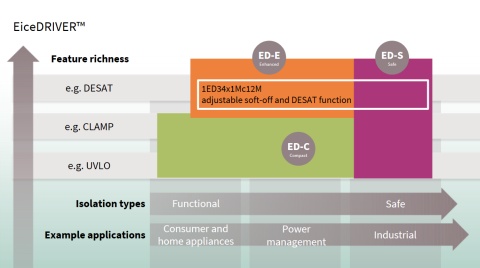
- The EiceDRIVER™ Enhanced X3 Analog family (1ED34xx), with DESAT (adjustable filter time), Miller Clamp, soft-off (adjustable current)
- Up to 9 A output current, 200 kV/µs CMTI, 30 ns Max. propagation delay matching, 40 V Max output supply voltage.
- Perfect for CoolSiC™ SiC MOSFET and IGBT7. VDE 0884-11 & UL 1577. For solar, EV charging, industrial drive, UPS, etc.
- The EiceDRIVER™ X3 Compact family (1ED31xx), with up to 14 A output current, 2300 V functional isolation, 200 kV/µs CMTI
- Show system benefit of Miller clamp, separate output, active shutdown, short circuit clamping, 7-ns prop. delay matching
- Perfect for CoolSiC™ SiC MOSFET and IGBT7. VDE 0884-11 & UL 1577. For solar, EV charging, industrial drive, UPS, SMPS
- The new EiceDRIVER™ X3 Digital family (1ED38xx), with I2C-configurability for DESAT, Soft-Off, UVLO, Miller clamp, two level turn off (TLTO).
- Up to 9 A output current, 200 kV/µs CMTI, 30 ns Max. propagation delay matching, 40 V Max output supply voltage.
- Perfect for CoolSiC™ SiC MOSFET and IGBT7. VDE 0884-11 & UL 1577. For solar, EV charging, industrial drive, UPS, etc.

You will have a glimpse of the different gate driver technologies available at Infineon and their benefits.
For a better understanding we will take a look at the optimization of external gate resistors to drive MOSFETs in a given application.
With this training, you will learn how to calculate a gate resistance value for an IGBT application, how to identify suitable gate driver ICs based on peak current and power dissipation requirements, and how to fine-tune the gate resistance value in laboratory environment based on worst case conditions.
Silicon Carbide MOSFETs bring a lot of opportunities to power electronics. However, how to achieve sufficient system benefits by using Silicon Carbide MOSFETs with suitable gate drivers? This training helps you to learn how to calculate a reference gate resistance value for your Silicon Carbide MOSFET; how to identify suitable gate driving ICs based on peak current and power dissipation requirements; and how to fine-tune the gate resistance value in laboratory environment based on worst case conditions.

Learn how Infineon’s EiceDRIVER™ galvanically-isolated gate driver ICs enable best-in-class efficiency while reducing the total system cost.

- EiceDRIVER™ isolated gate driver family use the state-of-the-art coreless transformer (CT) isolation technology
- The CT based isolated gate driver offers higher current, lower power consumption, better CMTI and best in class propagation delay matching
- Perfect for CoolSiC™ SiC MOSFET and IGBT7. VDE 0884-11 & UL 1577. For solar, EV charging, industrial drive, UPS, etc.
The EiceDRIVER™ Enhanced F3 family (1ED332x), with DESAT, Miller Clamp, soft-off up to 8.5 A output current, 300 kV/µs CMTI, 15 ns Max. propagation delay matching and 40 V Max output supply voltage.
Perfect for CoolSiC™ SiC MOSFET and IGBT7. VDE 0884-11 & UL 1577. For solar, EV charging, industrial drive, UPS, etc.
In this EiceDRIVER™ X3 digital isolated gate driver training you will learn how to install the software that aids you in the evaluation of X3 digital and its evaluation board.

