Power Stacks
In perfect harmony with Power Stacks - Heatsink & mounting concepts for bipolar semiconductors

How do you react to the increasing varieties and cost pressure in your business segment, and still keep focus on the quality requirements of the market?
With our comprehensive portfolio of stack assemblies with bipolar power semiconductors we offer our support as leading manufacturer of power semiconductors.
We develop yearly a huge number of customer specific stack assemblies from a large pool of well proven cooling and stack systems. More than 20 cooling block concepts out of three product lines enable the design of power electronic assemblies for voltages up to 20 kV and currents up to 14 kA. From more than 25,000 assembly variants we realize together with you the best fitting Power Stack specifically for your requirements.
The modular portfolio of our System Line covers solutions with thyristors and diodes and is optimized to the respective requirements. The design lines by basic building blocks support the requirements from semiconductors, applications and markets:
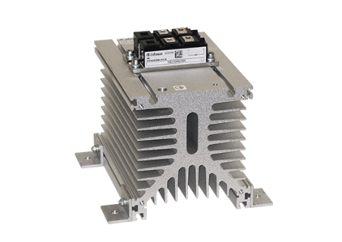
The System Line -
Compact Block
Designed for thyristor and diode modules in pressure contact or solder bond technology and defined by a potential free common compact heatsink.
Aircooled Blocks for Eco Blocks and Power Blocks
| Heatsink concept | Material | Cooling block name | Eco Block Power Block | No. of PB | Vop max [Vrms] | Power losses* |
|---|---|---|---|---|---|---|
| KM10 | AlMg | KM10 | PB20 | 1 | Depends on Power Block 1000-1300V |
40W (S) |
| KM | KM11 | PB20,34 | 3 | 200W (F) | ||
| PB50,60,70 | 1 | |||||
| KM14 | PB20,34 | 3 | 675W (F) | |||
| PB50,60,70 | 1 | |||||
| KM17 | PB20,34 | 3 | 900W (F) | |||
| PB50,60,70 | 1 | |||||
| KM18 | PB20,34 | 3 | 1250W (F) | |||
| PB50,60,70 | 1 | |||||
| KM Flat | KM12 | PB20,34 | 1 | 390W (F) | ||
| KM13 | PB50 | 3 | 1150W (F) |
* Total power losses for typical operational conditions for natural cooling (S) and forced air cooling (F) for the largest Power Block
Liquid cooled Blocks for Eco Blocks and Power Blocks
| Heatsink concept | Material | Cooling block name | Eco Block Power Block | No. of PB | Vop max [Vrms] | Power losses*) |
|---|---|---|---|---|---|---|
| KWo ** | Cu | KW50 | PB50 | 1 | Depends on Power Block 1000-1300V |
1200W |
| KW60 | PB60 | 1 | 1300W | |||
| KW70 | PB70 | 1 | 1850W | |||
| KWc | KW16 | PB60 | 1 | 1200W | ||
| KW30 | PB20 | 3 | 825W | |||
| KW34 | PB20,34 | 3 | 1185W | |||
| KW61 | PB20 | 9 | 3750W | |||
| KW65 | PB60 | 3 | 3950W | |||
| KW66 | PB60 | 4 | 5250W |
* Total power losses for typical operational conditions for natural cooling (S) and forced air cooling (F) for the largest Power Block
** Direct liquid cooled base plate
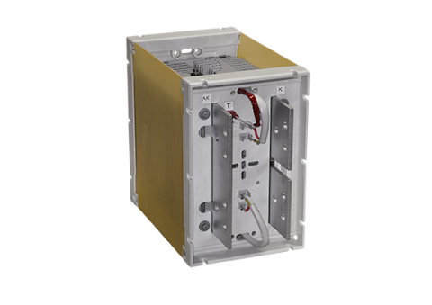
The System Line -
Frame Block
Designed for thyristor and diode discs and defined by high efficient two sided air cooling with perfect electrical conductivity in an insulating plastic frame.
Air cooled Blocks for Power Discs and Prime Discs
| Heatsink concept | Material | Cooling block name | Discs | Discs | Vop max [Vrms] | Power losses* |
|---|---|---|---|---|---|---|
| K017 | AlMg | K0,22F | 2 | 41, 50, 60 | 690 | 850W |
| K0,17F | 2 | 1150W | ||||
| K0,12F | 1 | 615W | ||||
| K008 | K0,11F | 3 | 41 | 1000 | 1450W | |
| K0.08.9F | 2 | 50, 60, 75, (100) | 2500 | 1450W | ||
| K0,08.7F | 2 | 1500 | ||||
| K0,08F | 2 | 1000 | ||||
| K0,048.7F | 1 | 1500 | 1400W | |||
| K0,048F | 1 | 1000 | ||||
| K0,05.8F | 1 | 2000 | 1225W | |||
| K0,05.7F | 1 | 1500 | ||||
| K0,05F | 1 | 1000 | ||||
| KE | KE02 | 2 | 120 | 2500 | 2900W | |
| KE01 | 1 | 120, 150 | 1850W | |||
| KS | AlMg Ni plated | KS12 | 2 | 120, 150 | 1500 | 3700W |
| KS11 | 1 | 1850W |
* Total power losses for typical operational conditions for forced air cooling.
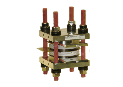
Tower Blocks – for thyristor and diode discs up to 8 kV
Designed for thyristor and diode discs up to 8 kV and defined by highest insulation capability, highest current capability and for series connection of discs. It is recommended for Pulsed Power applications and follows a tower design.
Liquid cooled blocks for discs
| Heatsink core name | Cooling block name | Discs | Disc size [mm] | Vopmax [Vrms] | Power losses [kW]* |
|---|---|---|---|---|---|
| KA20 (Cu) |
KA20.2-V | 2 | 41, 50, 60 |
690 | 1.5 |
| KA20.4-V | 4 | 3 | |||
| KA20.6-V | 6 | 4.5 | |||
| KC20.2-E | 1 | 1.6 | |||
| KC20.4-E | 2 | 3.2 | |||
| KC20.6-E | 3 | 4.7 | |||
| KD20.2-V | 2 | 3.3 | |||
| KD20.4-V | 4 | 6.7 | |||
| KD20.6-V | 6 | 10 | |||
| KD20.22-V | 2 | 41, 50, 60 |
3.3 | ||
| KD20.24-V | 4 | 6.7 | |||
| KD20.26-V | 6 | 10 | |||
| KA30 (Cu) |
KA30-V51 | 2 | 41 | 3.3 | |
| KA30-V61 | 48 | ||||
| K50V | 41, 50, 60 (75 height) |
||||
| K50V.1 |
*Total power losses for typical operational conditions for water cooling.
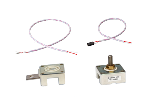
Accessories for
Blocks and Stacks
Accessories for blocks
- Temperature switch (Vop <=400V) and (Vop <=690V)
- Save Insulation for temp switch (Vop <=1250V)
- PT100 (Vop <=400V), PT1000 (Vop <= 400V), PT1000 (Vop <= 690V)
- NTC (Vop <= 400V)
- Magnetic firing circuits (firing transformers)
- Support for optical firing circuits (fiber and driver unit)
- Clamping devices
- Snubber circuits (TSE)
- Fuses for semiconductors
- Micro switches for fuses
- Hose barbs for liquid cooled heat sinks
- Support for hoses for liquid cooling, water collectors and mechanical set up in the cabinet
Accessories for stacks
- Magnetic firing circuits (firing transformers)
- Optical firing circuits (fiber and driver unit)
- Fans
- Input overvoltage protection
- Output overvoltage protection (DC side)
- Fuses for semiconductors
- Micro switches for fuses
- Power rails
- Support for liquid cooling cool back systems, hoses for liquid cooling, water collectors, mechanical set up in the cabinet, air stream monitoring, controllers
System Line - Details for Fittings (accessories)
| Overvoltage protection circuits | |||
|---|---|---|---|
| RC1 - TSE snubber circuit | RC2 - input snubber bridge | ARC - AC side RC snubber | DRC - DC side RC snubber |
| To avoid over voltages due to the reverse recovery charge effect every diode/thyristor is equipped with a parallel RC snubber which absorbs the charge/energy and which is a damping for possible oscillations. | To absorb surge voltages of higher magnitude inrushing from line an auxiliary rectifier is mounted in parallel to the rectifier. This auxiliary rectifier has a storage capacitor connected to the output which will absorb inrushing surges. Besides this there is also a restricted functionality as TSE. | To absorb surge voltages of lower magnitude inrushing from line RC snubber are placed phase to phase on the Ac side of the rectifier (recommended for DC currents up to 200A). | To avoid overvoltage at the DC side of a rectifier a RC snubber is mounted. This is helpful if there is no capacitor as DC link close to the rectifier output. |
| Benefits | Applications |
|---|---|
|
4 steps to your individual Power Stack
We support your requests flexible with building blocks:
- Find a module or disc which supports your application needs
- Choose one of the building blocks for basic circuits
- Define the stack from blocks according the application needs
- Add accessories according the applications needs


