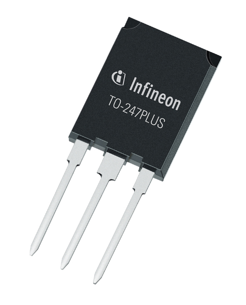
TO-247PLUS
Highest current density IGBT in TO-247PLUS Package
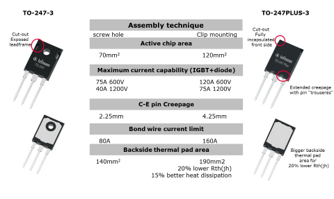
Highest current density up to 75 A 1200 V IGBT or 120 A 600 V IGBT copacked with a diode in TO-247 footprint, 20% lower Rth(jh), 15% better heat dissipation, fast clip assembly.

Comparisson TO-247 vs. TO-247PLUS
Discover the Families
1200 V IGBT in TO-247PLUS
Reducing number of power switches in parallel (at same Ic)
Due to bigger active chip area the new TO-247PLUS package can accommodate up to 75 A IGBT with 75 A diode. 3 pieces of 25 A in TO-247-3 can be replaced by 1 piece of 75 A in TO-247PLUS. Less paralleling benefits to easier IGBT control, higher system reliability, more compact design and lower bill-of-material (BOM).
Easy upgrade of the available designs for higher power output (Ic increase).
Higher current density of TO-247PLUS-3 allows one-to-one replacement of 40 A IGBT with 75 A IGBT keeping the same footprint and thermal conditions. IFX internal lab test showed Pout increase of 40% replacing in B6 Drive topology 40 A IGBT in TO-247-3 with 75 A IGBT in TO-247PLUS.
Easy upgrade of the existing design for higher power is possible. With little re-design efforts, low R&D costs and fast re-design time.
Improved system thermal management – Tj and Tc reduction (at same Ic)
35% bigger backside thermal pad area of TO-247PLUS package results in 20% lower Rth of the package and contributes to 15% better heat dissipation. Replacing 40 A IGBT in TO-247-3 with same current 40 A IGBT but in TO-247PLUS package allows to reduce junction temperature Tj. Lower junction temperature Tj reduces thermal stress on IGBT, allows to use smaller heatsink or less powerful cooling fan leading to smaller system dimensions at lower BOM.
Maximize flexibility of your design with the TO-247PLUS package!
Use in Application TO-247PLUS
| System Nominal current Ic | Available solution | Available solution with TO-247PLUS | Replacement Ratio | Benefits using TO-247PLUS-3 |
| Increased power density - increasing power output | ||||
| 40 A → 75 A | IKW40N120T2 | IKQ75N120CT2 | 1:1 |
|
| IKW40N120H3 | IKQ75N120CH3 | 1:1 | ||
| Reduced paralleling keeping the same system current | ||||
| 25 A → 25 A | 3 x IKW25N120T2 | 1 x IKQ75N120CT2 | 3:1 |
|
| 25 A → 25 A | 2 x IKW25N120T2 | 1 x IKQ50N120CT2 | 2:1 | |
| 40 A → 40 A | 2 x IKW40N120T2 | 1 x IKQ75N120CT2 | 2:1 | |
| Improved thermal management, Tj reduction | ||||
| 40 A → 40 A | IKW40N120T2 | IKQ40N120CT2 | 1:1 |
|
| IKW40N120H3 | IKQ40N120CH3 | 1:1 | ||
600 V IGBT in TO-247PLUS
What are the advantages of 100 A and 120 A IGBT co-packed with full rated diode in JEDEC standard TO-247PLUS?
The advantages are multiple, depending on the need – power output or power density increase, size and cost reduction, better thermal performance, higher reliability and longer lifetime.

Easy upgrade of the available designs for higher power output.
One-to-one replacement of 75 A IGBT with 120 A device allows up to 40% power output increase keeping the same footprint and thermal conditions.
Increased system power density, reducing the PCB footprint, reducing the cost.
Keeping nominal current Ic in the system the same, 3 pieces of 75 A IGBT in TO-247 can be replaced with 2 pieces of 120 A IGBT in TO-247PLUS.
Improved thermal conditions for higher reliability and longer lifetime of the IGBT.
35% bigger thermal pad area of TO-247PLUS contributes to 10% -15% better heat dissipation allowing lower junction temperature Tj.
Maximize flexibility of your design with the TRENCHSTOP™ in TO-247PLUS package.

