Battery protection units (BPU)
Solutions that allow easy design-in and ensure safe charging and discharging - prevent damage and failures
The high power density of Lithium-Ion batteries has made them very popular. However, the unstable behavior of Lithium-Ion cells under critical conditions requires them to be handled with care.
That means a Battery Management System (BMS) is needed to monitor battery state and ensure the safety of operation. BMS is typically equipped with an electronic switch that disconnects the battery from charger or load under critical conditions that can lead to dangerous reactions. A battery protection unit (BPU) prevents possible damages to the battery cells and the failure of the battery.
Such critical conditions include:
- Over-charge: is when the battery is charged over the allowed maximum capacity.
- High & low temperature: is when the internal temperature of the battery cells exceeds their safe operational temperature ranges.
- Over-discharge: is when the battery is discharged under the allowed minimum capacity.
- Over-current: is when the battery is exposed to a short circuit condition or a high inrush turn-on current.
- Reverse polarity: is when the battery terminals are wrongly plugged into the device.
Failing to disconnect or manage the battery during such conditions can lead to the following problems:
- Thermal runaway: Often is due to over-charging or over-heating of the battery. The overheating can be due to a rise in the ambient temperature or due to charging/discharging the batteries with high current rates. Thermal runaway not only damages the battery cells but also can lead to fires.
- Death of the cell. Often is due to the discharge of Batteries below its specified thresholds.
- Damage of load device: Often is due to either bad inrush current management or reversing the battery polarity.
In the sections below, we show the different battery protection topologies and their advantages and disadvantages. Additionally, we added application notes and product selection guides to help the customers find the best protection solution for their battery packs.
Key benefits of Infineon battery protection solution
- Higher performance with lower RDS(on) Wider safe operating area (SOA)
- Cheaper solutions with a more compact bill of material and more effective parallelization solutions
- Short circuit protection with higher peak current rates
- Turn-on and turn-off solutions tailored to applications needs
- Up to 600 V MOSFET protection solutions (including single- and multi-module)
Battery pack architectures
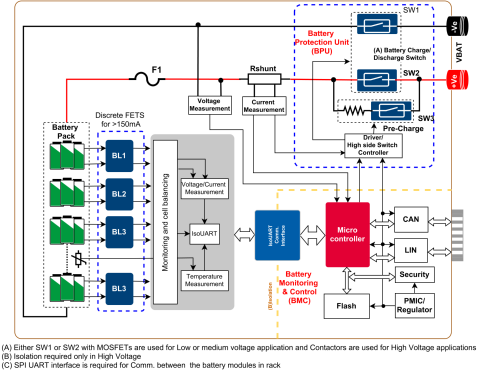
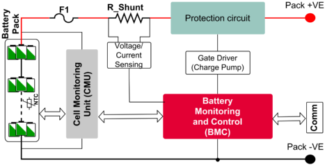
Single-module batteries are typical for applications with voltage range not exceeding 150 V, such as battery-powered tools, vacuum cleaners, multicopter, robots, e-scooters, e-bikes, low voltage telecom, and server UPSs.
Discover the best-fit products for your design for single-module batteries.
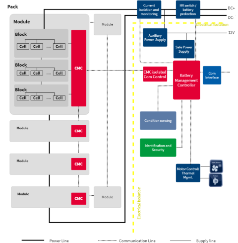
Multi-module batteries are typical for applications with high-voltage batteries, including automotive, e-forklifts, e-boats, residential and utility size energy storage systems and UPSs.
Discover the best-fit products for your design for multi-module batteries.
Protection topologies
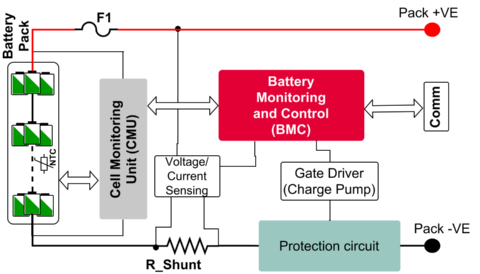
In the low side protection, the disconnect MOSFETs are connected in series with negative terminal of the battery pack.
Benefits: Easy to implement, requires no charge pumps for the gate drivers.
Drawbacks: Hanging ground → potential of ground bypass via the battery housing and impact on communication & operation.
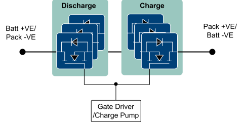
In common source configuration, the MOSFETs are connected in series with their sources connected to each other and Drain terminals of the MOSFETs forms in and out of the protection Circuit. Such a configuration of the MOSFETs can also be referred to as a back-to-back configuration.
Benefits:
- Can switch faster.
- Less expensive.
- Need only one charge pump or isolated supply is required.
- Need only one gate driver to drive the two MOSFETs.
- Less complex design.
Downsides:
- Less thermal Dissipation area for MOSFETs with standard Drain down packages. Since the heat generated by MOSFETs dissipates into the copper, which is connected with the control and sensing circuits. Thus affecting the accuracy and efficiency of the control and sensing solution.
- In case of a failure, while using a single gate driver, both MOSFETs will likely fail simultaneously.
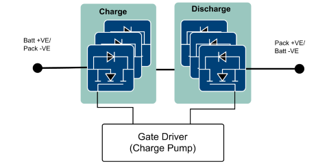
In common drain configuration, the MOSFETs are connected in series with their drains connected to each other and source terminals of the MOSFETs forms in and out of the protection Circuit. Such a configuration of the MOSFETs can also be referred to as a back-to-back configuration.
Benefits:
- Possible to control the FETs independently.
- Easy to implement safe commutation techniques.
- Higher safety standard, due to need separate gate drivers to drive the MOSFETs.
Drawbacks:
- Need a charge pump to drive both MOSFETs.
- More complex design.
In this type of topology, the battery charger and the load ports are separated. Such a topology is commonly used, when:
- the charging currents and discharging currents are different (charging currents are usually much lower than discharging currents).
- the battery is separated from the load when charged.
Benefits:
- Lower thermals due to lower path resistance.
- Requires fewer MOSFETs.
Drawbacks:
- Easy to bypass the reverse polarity protection.
- Source to source topology could only be used on the high side, whereas drain to drain could be used on the low side.
| High Side | Low Side |
Protection functionalities and solutions

Battery protection enhances the useful operating life of lithium-ion batteries by protecting the battery pack against charge current, discharge current, and pack short fault conditions. Learn more about battery protection.
Inrush currents arise during turn on, mainly when the battery is first connected to the load. The inrush currents can get high enough to either blow off the protection fuse or lead to switching off of the protection MOSFETs due to false indications of overcurrent or short circuit Alarm. An inrush current limiting circuit limits the inrush current during the turn-on phase and protects both the battery and the load. The pre-charge circuit is required whenever any of the following conditions is true:
- The load has high input capacitance, which will be damaged by the inrush current.
- The main fuse will blow off if the turn-on current exceeded the fuse's limit.
- The contactors, if present, will be damaged by the inrush current.
- The battery cells are not rated for the inrush current.
- The MOSFETs are not rated for the inrush current.
The precharge circuit often consists of a MOSFET with high resistance path
| With P-MOSFET | Precharge with N-MOSFET |
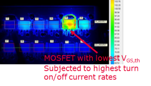
During short circuit conditions, the MOSFETs must not only withstand the rise in the current but also possibility of avalanching during turn off. The MOSFETs and circuitry which detect faults and disconnects the battery or load are referred to as eFuse. Avalanching of an eFuse might occur since during a short circuit the MOSFET needs to be turned off fast. This in turn will result in short and high current pulses that flow into the inductance, which is created by the wires connecting the battery pack with the load - and by the load itself. The parasitic inductance can induce enough voltage to result in the Avalanching of the MOSFETs which will turn the loads' inductance into a voltage generator, ramping up the voltage across the protection solution beyond the maximum allowed voltage. Infineon OptiMOS and StrongIRFET technology offer wide Safe Operating Areas (SOA) and rugged linear mode devices to enable safe and reliable eFuse functionality. Additionally, Infineon devices have low ΔVGS,Th, which enables devices to share equal current between parallel MOSFETs during switch on & switch off transients.
- Get an overview of the main feature set of this 48-volt capable EiceDRIVER™.
- Understand its different integrated protection mechanisms.
- Get an overview of the main features of this flexible EiceDRIVER™ device
- Understand its different integrated protection mechanisms

