TRAVEO™ T2G cluster devices feature a graphics subsystem that allows displaying graphical content.
Streamline Your Project with Infineon's Software Solutions
To help you harness the full potential of our hardware, Infineon offers a comprehensive range of software products. These solutions not only enable our hardware features but also provide a seamless way to get your project up and running quickly. Developed with Automotive SPICE compliance in mind, our software products are perfectly suited for automotive production use. Plus, many of our software products offer AUTOSAR integration, a popular choice for our customers.
Request a free evaluation license for TRAVEO™ Software
- To request a free 3-month evaluation license or request access to an existing one for the following Software packages: TRAVEO™ T2G - AUTOSAR MCAL drivers, AUTOSAR Complex Device Drivers, AUTOSAR Self-Test Library, Graphics drivers, Safety Signature Driver, Dynamic Warping Library click here.
The Graphics Driver
The display module oversees the operation of the display controller(s) inside the TRAVEO™ T2G GPU. Multiple effects can be applied in real time to the active video stream that is to be shown on the output display(s):
The video subsystem has one or two display controllers that can be connected to one or two displays, respectively. Each display has a constant background color.
The content of up to 26 image buffers can be shown in individual rectangles (called "windows") on the displays.
These windows are arranged in a defined z-order. Overlapping rectangles can be drawn opaque (only the higher-level window is visible), or they are blended into the lower-level frame content by using up to five blend units (called "Layers").
The buffer that is displayed in a window can be a static frame buffer that contains the whole image data shown in the window during one display frame period. That image data can be a bitmap read from the read-only memory, a video frame provided by a camera, or an image that was rendered previously by the Blit Engine of video subsystem. Alternatively, a window can show the contents of a line buffer that contains only a slice of the image data that is dynamically rendered by the Blit Engine while it is displayed. The latter is called OTF (on-the-fly) rendering.
The Blit Engine is a hardware IP that efficiently performs pixel operations on two-dimensional memory blocks. It reads simultaneously from up to three source rectangles, executes pixel processing operations on these, and stores the result in another rectangular memory region. There are number of operating modes that are made available by the Blit Engine.
The drawing engine is a video subsystem component for hardware-accelerated outline vector drawing. Outline vectors are most frequently used for font rendering; the drawing engine is optimized for such use cases. However, it is not limited to font rendering and can be used for any outline vectors. The outline curves must be supplied as vector data. The drawing engine generates an intermediate alpha bitmap that will be used as the alpha mask for blit operations.
The capture component provides an API to capture a video stream to memory or display.
The Synchronization API and several other APIs provide mechanisms to synchronize the processing units. This is done through sync objects. A sync object is defined by two parameters: the node (the identifier of the event that one wants to synchronize with) and the value (the status of the event supervising activity). Such a sync object must be initialized first. To use a sync object, the following sequence must be called:
- Define a sync object for a processing unit and a condition.
- Use this sync object to control a different processing unit. The execution of all subsequent operations of this unit will be blocked until the sync condition becomes true.
This API provides functions to configure the reporting of ERROR, WARNING, and INFO messages. The level of these messages can be specified per module.
The writeback API provides the possibility to store one frame of a display stream in a surface buffer.
TRAVEO™ T2G Safety Signature Driver
The signature unit calculates CRC checksums over selected areas of a display stream that is created by the video subsystem of the TRAVEO(TM) T2G MCU. It can compare the calculated checksums with reference checksums. When a calculated checksum differs from its reference checksum, the signature unit can notify the Safety Signature Driver which can pass the notification to the application level. After the signature unit has calculated checksums on the contents of the display stream, that stream passes through one more hardware unit, which is called "Timing Controller". To ensure the integrity of the display stream at this stage, Safety Signature Driver can monitor the contents of the configuration registers of the Timing Controller. If a modification of any of the monitored registers is detected, the Safety Signature Driver notifies the application software on the error condition.
JPEG Decode Driver
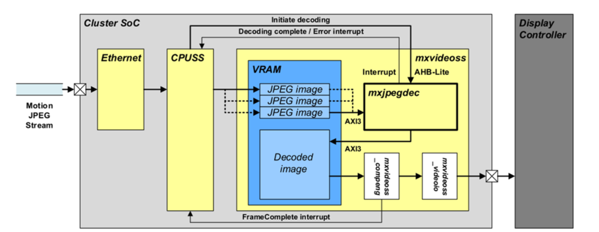
Some TRAVEO™ T2G devices are equipped with a hardware unit for decoding JPEG images.
Use cases include that a motion JPEG stream is routed to the TRAVEO™ device via ethernet and the video stream is decoded in real time and displayed.
Using the JPEG decoding system, a video performance up to 2880x1080@60Hz for TRAVEO™ T2G-C-2D-6M-DDR can be achieved.
The driver support configuration setting such as:
- Packed destination buffers for YUV 4:4:4, gray and RGB (8 and 24bpp)
- Semi-planar destination buffers for YUV 4:2:2, 4:1:1 and 4:2:0 (8 and 16 bpC
- Chroma up-conversion to 4:4:4 for all formats by sample replication
And offers:
- Control of MMIO registers and interrupt for SW and
- Detection of corrupt data and bus errors.
Dynamic Warping Library
TRAVEOTM T2G devices, that have a graphics IP inside are supported by an appropriate Graphics Driver (GFX Driver). This Graphics Driver together with the underlying graphics IP is able to apply in real-time a given image warp coordinate buffer describing the distortion of the output image. With its help the output content thereby achieving a real-time visual output warp effect.
The Dynamic Warping Library works independently to this Graphics Driver allowing the generation of such a warp coordinate buffer from a given warp distortion grid with lower resolution, so the application is able to recalibrate the warping process in real-time if the user’s eyesight perspective changes